Steel Selection
GLS TPEs are generally non-abrasive and non-corrosive. The selection of tool steel will depend on the quantity and quality of parts to be produced. For high volume production, the initial expense of quality tooling is a sound investment.
A wide variety of tool steels are available for injection mold construction. The table below lists the properties of common tool steels and the typical mold components for which they are used. Soft metals, such as aluminum and beryllium copper, can be used for prototype parts or short production runs up to 10,000 parts.
Some part designs may benefit from the use of higher thermal conductivity materials such as beryllium copper. This material is less durable than steel and may hob or wear faster than steel if used at the parting-line. Beryllium copper can be used for inserts, slides or cores to increase heat transfer rates and reduce cycle times. In cases where there is a long draw core, a fountain-type bubbler may be beneficial.
|
Steel Type
|
Steel Properties
|
Mold Component
|
|
P-20
|
Pre-hardened, machines well, high carbon, general-purpose steel.
Disadvantage: May rust if improperly stored.
|
Mold bases, ejector plates, and some cavities (if nickel or chrome plated to prevent rust).
|
|
H-13
|
Good general purpose tool steel. Can be polished or heat-treated. Better corrosion resistance.
|
Cavity plates and core plates.
|
|
S-7
|
Good high hardness, improved toughness, general-purpose tool steel. Machines well, shock resistant, polishes well.
Disadvantage: Higher cost.
|
Cavity plates, core plates and laminates, as well as thin wall sections.
|
|
A-2
|
Good high toughness tool steel. Heat-treats and polishes well.
|
Ejector pins, ejector sleeves, and ejector blades.
|
|
D-2
|
Very hard, high wear characteristics, high vanadium content, somewhat brittle.
Disadvantage: Difficult to machine.
|
Gate blocks, gib plates to prevent galling, gate blocks to prevent wear.
|
|
420 SS
|
Tough corrosion resistant material. Heat-treats and polishes well.
Disadvantage: High cost.
|
Cavity blocks, ejector pins, sleeves, etc.
|
Mold Surface Treatment
- In general, an EDM surface will produce a good texture and may improve release from the tool during part ejection. Matte or textured surfaces can also help to hide any flow marks or other surface defects.
- If a matte finish similar to that of a thermoset rubber is required, a rougher mold texture should be used (or Versalloy TPV alloys, which naturally produce a matte surface).
- Vapor honing, sand or bead blasting and chemical etching are used to produce textured surfaces with varying degrees of gloss and appearance.
- To produce a glossy surface, a polished mold is required and an unfilled grade should be used.
- A highly polished tool and a transparent material are required to produce a part with good clarity.
- To aid in release, the cavity or core may be coated with a release coating such as PTFE impregnated nickel after it has been given a sandblast or EDM finish.
Sprue and Sprue Puller Design
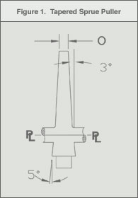
The sprue should have sufficient draft, from 1° to 3° to minimize drag and sprue sticking. Longer sprues may require more taper (3° - 5°), as shown in Figure 1. Typically, the sprue diameter should be slightly larger than the nozzle diameter. An EDM finish is acceptable for most GLS TPE formulations. Permanent surface lubricant treatments have also been used successfully.
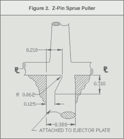
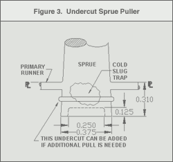
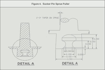
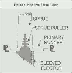
Sprue puller designs vary with the hardness of the material. The different sprue designs possible are shown in Figures 1 through 5.
The typical sprue designs for various TPE hardness values are shown in the table below:
|
Typical TPE Hardness Range
|
Most Common Sprue Puller Types
|
Figure
|
|
> 50 Shore A
|
Tapered, Pin, Z-Type
|
1, 2 and 4
|
|
40-70 Shore A
|
Undercut
|
3
|
|
5-40 Shore A
|
Pine Tree
|
5
|
Hot sprue bushings and extended nozzles may be used with GLS TPEs. In many molds, the sprue is the thickest wall section in the mold and will control the minimum cooling time. The use of a hot sprue, which may be viewed as an extension of the machine nozzle, can sometimes reduce cycle time. Extended machine nozzles may also be used to reduce sprue length and size. When hot sprues are used, the machine nozzle tip should be a free-flow nozzle rather than a reverse tip.
*Spiral flow tests performed using 0.0625" thick x 0.375" wide channel at 400°F.
For spiral flow information about a specific grade or additional details about the spiral flow test procedure, please refer to the TPE Tip #7.
Conventional Runner Design
A balanced runner configuration is critical to achieve uniform part quality from cavity to cavity. In a balanced runner system, the melt flows into each cavity at equal times and pressure. The runner balance can be designed by using computer mold-flow analysis programs and verified by performing short-shot studies.
An unbalanced runner may result in inconsistent part weights and dimensional variability. The cavity closest to the sprue may be overpacked and flashing may occur. As a result of overpacking, parts may also develop high molded-in stresses, which lead to warpage. Examples of balanced runner systems are shown in the figures below:
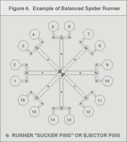
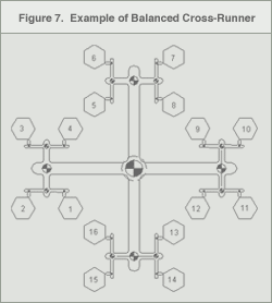
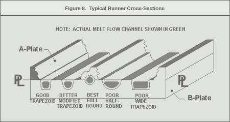
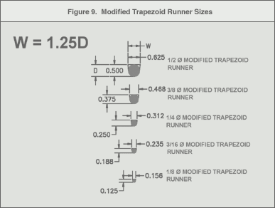
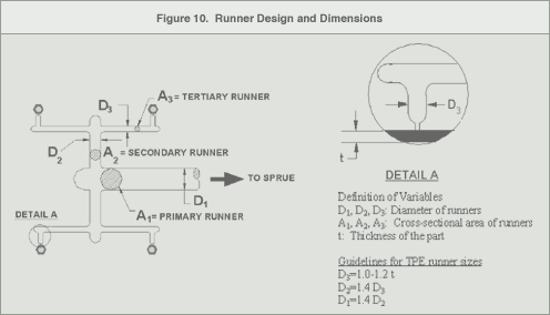
Figure 8 shows different runner cross-sections and their associated efficiency. Full-round runners have the least resistance to flow and surface area, allowing the material to stay molten longer. The second most efficient runner cross-section is the modified trapezoid. This runner geometry most closely simulates a full round runner, but only requires machining in only one plate. Figure 9 shows typical ball cutter dimensions and the corresponding modified trapezoid runner sizes. Figure 10 illustrates typical runner dimensions.
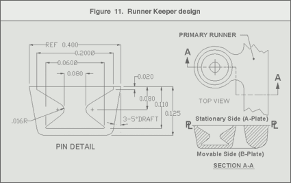
Runner Keepers
Runner keepers or sucker pins provide undercuts to keep the runner on the desired plate but should not restrict material flow through the runner. Figures 8 and 9 show typical locations for runner keepers and sucker pins. Figure 11 illustrates an example design of a runner keeper.
Gate Design and Location
Most conventional gating types are suitable for processing GLS TPEs. The type of gate and the location, relative to the part, may affect the following:
- Part packing
- Gate removal or vestige
- Part cosmetic appearance
- Part dimensions, including warpage.
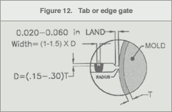
Tab/Edge Gates
Tab or edge gates (Figure 12) most commonly utilize a conventional sprue and cold runner system. Advantages of edge gates are ease of fabrication, modification and maintenance.
- The gate depth (D) should be 15% - 30% of the wall thickness at the gate entrance. Common practice is to start "steel safe".
- A good starting point for the gate width should be 1.0 - 1.5 times the gate depth.
- The gate land should be equal to or slightly longer than gate depth.
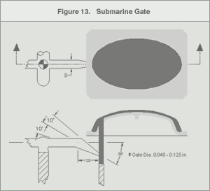
Submarine / Tunnel Gates
Submarine or tunnel gates are self-degating. During part ejection, the tool steel separates the part and the runner. Figure 13 shows a typical design of a submarine gate. Cashew type submarine gates should not be used for medium to soft hardness TPEs due to their high coefficient of friction and high elongation.
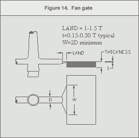
Fan Gates
A fan gate is a streamlined variation of a tab gate (Figure 14). The fan gate distributes material into the cavity more evenly, thus it is normally used in parts that require a high degree of flatness and absence of flow lines. It also minimizes the possibility of gate pucker or part warpage.
Sprue or Direct Gate
The sprue or direct gate is often used on prototype parts because it is inexpensive. This type of gating is not recommended for GLS styrenic TPEs because of their high elongation. In addition, the sprue will need to be trimmed thus appearance quality of the part is usually poor. If sprue gating is selected, care should be taken to keep both the sprue length and diameter as short and small as possible.
Diaphragm Gate
The diaphragm gate is used to maintain the concentricity of round parts. It allows even flow into the cavity and minimizes the potential for knit lines. Due to anisotropic shrinkage, flat round parts using center or diaphragm gating may not lay flat. A ring gate may also be used on the outside of a circular part.
|
Gate Type
|
Advantage
|
Disadvantage
|
|
Edge/Tab/Fan Gate
|
- Appropriate for flat parts
- Easy to modify
|
- Post-mold gate/runner removal is difficult
- Poor gate vestige
|
|
Submarine Gate
|
- Automatic gate removal
- Minimal gate vestige
|
- More difficult to machine
|
|
Diaphragm Gate
|
- Concentricity
- Appropriate for round parts
- No knit lines
|
- Scrap
- Post-molding gate removal
|
|
Pin gate (3-plate)
|
- Automatic gate removal
- Minimal gate vestige
- Localized cooling
|
- Requires floater plate
- More scrap
- Higher tool cost
|
|
Valve gate (Hot runner systems)
|
- Minimal gate vestige
- Positive shut-off
- Minimizes post pack
|
- Higher tool cost
- Higher maintenance
- Only for hot runner systems
|
Gate Location
Styrenic TPEs are anisotropic, thus they have different physical properties in the flow direction versus the cross-flow direction. Depending on the product's intended usage, these property differences could be critical to the performance of the final part. As a result, the anisotropic nature of the styrenic TPE needs to be taken into consideration when determining the gate location on the part.
The material flow may be estimated by eye or by using flow analysis programs. For higher shrinkage grades, the part may shrink near the gate, which causes "gate pucker" if there is a high molded-in stress at the gate. If filling problems exist in thin walled parts, adding flow channels or minor changes in wall thickness can alter the flow. In some cases, it may be necessary to add a second gate to properly fill the parts.
Recommended Gate Locations:
- At the heaviest cross section, to permit part packing and minimize voids and sink.
- To minimize obstructions (flowing around cores or pins) in the flow path.
- To minimize jetting.
- Where residual molded in stress around the gate will not affect part function or aesthetics.
- To minimize flow marks in cosmetic areas.
- To minimize potential knit lines.
- To allow easy manual or automatic degating.
- To minimize flow path length.
Mold Venting
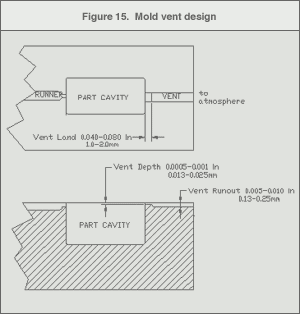
Mold venting is critical to the quality and consistency of the finished part. Venting is required to allow the air in the sprue, runner and cavity to leave the tool as the melt flows into the cavity. Inadequate venting may cause short-shots, poor surface appearance, or weak weld-lines. Potential air traps in the part design can be predicted by flow simulation software. Once the tool has been built, short-shot studies can be used to find the critical venting areas.
- Vents should be placed at the last place to fill and in areas where weld lines occur.
- The typical vent size for GLS TPEs, is 0.0005" - 0.0010" (0.012 mm - 0.025 mm) with a 0.040" - 0.060" (10 mm - 15 mm) land.
- Past the land, the vent depth should be increased to 0.005" - 0.010" (0.12 mm - 0.25 mm) to provide a clear passage for the air to exit the tool (Figure 15).
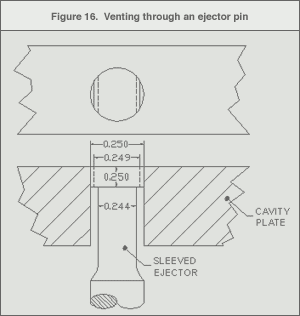
- Venting in areas below the parting line can be accomplished by allowing the ejector pin to be 0,001 loose on each side (Figure 16).
- Venting of ribs or pockets can be achieved by venting down an ejector pin, or with the use of porous mold steels.
- Ejector pin vents are self-cleaning, but they should be wiped once a day to remove build-up. Porous plug vents need to be replaced or dismantled and cleaned when they become clogged.
Part Ejections
Part ejection is more difficult in long draw areas. Ejector pins should be located at runner transitions and in areas of the part where they will not affect the aesthetics. Ejector blades, ejector sleeves and stripper rings can be used for part ejection.
Use the largest diameter pins possible to minimize pin push-through marks. Larger pins also allow the ejection of warmer parts, which can reduce cycle time. Use a 3° - 5° draft per side on all long draw areas.
Air ejection and the use of poppet can help strip large undercuts providing the material has room to deform when the air is applied. Mold surface texturing and special mold surface treatments can also help to pull the parts from the "A" half. Advancing cores are used usually when trying to strip large internal undercuts.
Mold Cooling
- The mold should have adequate cooling to optimize cycle time.
- The use of mold materials with high heat transfer, such as beryllium copper, can be used to cool slides or inserts.
- Commercially available fountain-type bubblers may also help to cool long cores.
- Separate chillers for the movable and stationary sides are suggested. This allows the processor to use differential cooling to help retain the parts on the movable ("B") plate.
- Connecting cooling lines from the A to the B plate should be avoided.
Hot Runner Systems
The differences between hot runner systems, cold runners and hot sprues are summarized in Table 5. GLS TPEs are quite heat stable and are used successfully in hot runner tools today.
Selecting a particular type of hot runner system is influenced by the product design and production requirements. There are many hot runner component and tool manufacturers available. If possible, utilize a system or component supplier with experience in styrenic TPEs. SBS TPEs can crosslink (forming gels) if they are held at high temperatures for too long a period of time, therefore hot runner tools are not recommended for these materials.
A comparative assessment of hot runner systems is summarized in the table below:
|
System Type
|
Advantage
|
Disadvantage
|
|
Cold runner
|
- Lower tool cost
- Easily modified
- Enables use of robotics
|
- Typically governs cycle time
- Potential for cold slugs
- Potential for sprue sticking
- Scrap (though regrindable)
|
|
Hot Sprue or Extended Nozzle
|
- Faster cycle
- Minimizes scrap
- Easily maintained
- Better temperature control
|
- Higher tool cost
- Potential heat degradation for SBS TPEs
|
|
Hot Runner
|
- No runner scrap
- Faster cycle time
- Precise temperature control
|
- Highest tool cost
- Purging
- Material degradation
- Maintenance
|
Manifold Design
- Externally heated systems are best.
- Internally heated manifolds are not suitable for TPEs. These systems typically have hot spots and stagnation zones that cause partially solidified material to cling to the cooler manifold walls.
- For maximum flexibility, the design should be naturally or geometrically balanced. Rheological balancing is possible, but only for a specific grade or rheometric curve.
- All passages should be highly polished circular cross sections with gentle bends to minimize the possibility of stagnation zones.
- In order to maintain high shear, minimize residence times and promote flow, the passages should have a diameter of 0.250" to 0.375".
- Individualized zone controls for the hot runners are recommended to allow the operator to adjust the balance slightly to make the parts more uniform.
Hot Runner Gate Design
Valve Gates
Valve gates offer the best solution for high production parts where surface quality is critical, such as medical and cosmetic products. Since valve gates leave only a slight ring on the part, gate vestige is minimized.
Further improvement can be obtained by positioning the valve recessed below the part surface or concealing the gate in the part detail for aesthetic products. An example of a hot runner system with a valve gate is shown below:
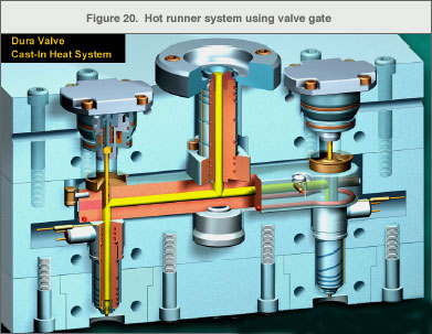
Image provided by Mold-Masters Limited, Dura is a registered trade-mark of Mold-Masters Limited
The gate diameter of a valve gate should be approximately 0.030" to 0.125", depending on the size and thickness of the part.
Valve gates do not require the material in the part to freeze before the valve is closed and hold pressure is released. Therefore, the screw recovery for the next cycle can start earlier and the total cycle time may be decreased.
Valve gate elements need to be insulated from the mold plates to maintain proper temperature control. Due to the low viscosity of some GLS grades, properly maintained tight valve gates are required to prevent leakage or hair flash.
Hot Tip Gates
Hot tip gates are suitable for GLS TPEs, but they will leave some gate vestige (which can be as high as 50% to 75% of the gate diameter). Vestige can be minimized by slightly recessing the gate below the part surface. The land length of the hot tip should be less than the diameter of the gate.
The elements of the hot tip should be properly insulated from the mold plates and cavity. In order to achieve this, the land length of the gate may need to be lengthened and a portion of the land should be part of the cavity.
All passages within the tip should be highly polished and streamlined to minimize stagnation and degradation zones. The efficiency of the design may be verified by recording the time it takes to make a complete color change while producing parts. This demonstrates whether there is any residual dead zone material that continues to enter the melt stream.
For hot tip gate systems, there should be a delay long enough for the part to set up completely before mastication is initiated for the next cycle. Without a delay, the parts may become overpacked. This is particularly important for low hardness, high flow materials. To reduce overpacking for thick-walled parts with large gates, use minimal back pressure during mastication.
Since TPEs are slightly compressible in the molten state, larger runner volumes can cause hot tip gates to drool after the mold is opened. To prevent drool, the runner system should be minimized and the melt decompressed before the mold opens.
